CHUA
Nothing has hit the site for a while.
The reason is simple: life got in the way, as always, without any warning. A few personal matters occupied my head, and the work side was intense. I simply couldn’t find the energy to write. Silence is sometimes not a choice—it’s just the only state the current mood allows.
My plan was actually different: to finish the Analog PC project and write a comprehensive article on it.
The schematic is done. Everything is complete on paper—but there was at least a 2-3 week marathon of soldering waiting for me, one that required patience, and I just didn’t have that patience to summon that day. I need to resolve a few things regarding life first.
So, the Analog PC was set aside. Even though the schematic is ready. (KiCad FTW.) No one died, the universe didn’t give a damn—the project simply entered standby mode.
Instead, I occupied myself with something smaller, but just as philosophical.
Actually, the goal was still the Analog PC. And there is an immutable requirement in the nature of analog work: symmetrical power. A power supply with both + and - voltages.
You might ask: “Is there such a thing as negative voltage?“
1. “Is There Such a Thing as Negative Voltage?”
The short answer: no, there isn’t. The long answer, as always, is more interesting—and somewhat comforting, because it’s not as dramatic as it seems.
Voltage isn’t an absolute magnitude anyway. It is the potential difference between two points, that’s all. When you say “5V,” you’re actually saying “5V higher relative to a certain point.” We call that reference point ground (GND, VSS, 0V)—the only fixed point the circuit gives you, and even that is chosen arbitrarily.
No matter where you place the reference, the measurement takes shape accordingly. At the tip of a laptop adapter, for instance, there is a 19V difference between the + and - wires. If you consider the - wire as 0V, the + wire is +19V. But if you take a reference from the very middle—then one side is +9.5V, and the other is -9.5V. The voltage didn’t change, only where you are looking from changed—it’s a matter of perspective, just like most social arguments. (No, not the daytime talk shows.)
What is done in a symmetrical power supply is exactly this: dividing a single-ended source in half with a virtual ground to make one side +12V and the other -12V.
We carry the oldest and most honest example of this in our pockets: batteries in series.
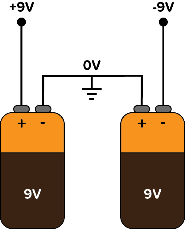
If you connect two batteries in series, you can treat the connection point between them as the “midpoint” and draw a ground from there. At that moment, one battery becomes + and the other - — neither of them changed; you just decided where to look from.
Voltage itself is exactly that: the potential difference of an electric field. Think of it as a kind of pressure for the EM force.
Imagine standing on the seashore. A point above your head is +x to you—up there, potential is high. The bottom of the sea is -x—down there, potential is low. But this “up” and “down” are not absolute; they are relative to you. It’s the same thing.
Now you might rightfully ask: “So what? Why do we need this?”
Good question. Because in many places, it really isn’t needed. The digital world gets by with 0s and 1s, living entirely on the positive side—a comfortable, easy, one-way life. Nobody falls into the negative there. (xD that’s why it isn’t the real world.)
But analog work doesn’t work that way. (that’s the real world.)
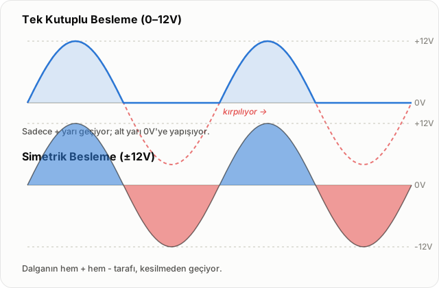
What you deal with in an analog circuit is a wave. A wave doesn’t just go up; it also goes down—it has a trough just as it has a peak. If your supply is stuck between 0-12V, you have no room to process the bottom half—the negative part—of the wave. The circuit will either clip it or show it with a meaningless DC offset. All or nothing—there is no third option.
That’s why we need negative voltage: to process the negative side of the wave without clipping or distorting it.
And there is a price for this. Finding a ready-made adapter or circuit that produces negative voltage on the market is incredibly difficult. It’s niche. Nobody is printing -12V for you and selling it—like motivational speeches, the market loves positive thinking. You have to generate the negative yourself—as you are always doing.
I was aware of this when I started the Analog PC. Negative voltage was a must; no room for debate.
The solution sounded simple: LT1054. This small IC takes the positive voltage you have—up to 15V—and spits out the negative of the same magnitude. You give it 15V, you get -15V. Like magic. But there is no free magic, dammit; the bill always comes due.
The LT1054 has a current limit: it chokes at 30-40mA. If you ask for more than the limit, the chip shrugs its shoulders and says, “That’s all I can do” 🤷—at least it’s honest; most people don’t even tell you that much.
Here is the problem: the analog world of the 1970s and 80s is not gentle at all regarding current. The op-amps of that era are current monsters—nobody told them “slow down, man,” and even a single one of them can draw 10-20mA by itself. If you put a few of them in your circuit, the LT1054’s 30-40mA budget is exhausted before it even starts talking.
My plan was actually clean: power the Analog PC from 5V. First boost the 5V to 15V, pump out a -15V with the LT1054 in return, and finally pass both through a linear regulator to reduce them to a smooth ±12V.
That was the job on paper. Then thermodynamics, as always, quietly intervened—without asking for any permission.
2. When Thermodynamics Intervenes
Let’s sit down and calculate. There are a few current-monster op-amps in the circuit (10-20mA each), plus the LT1054’s own demand (5-10mA). Sum it up, and the load actually drawn from the +15V line is roughly 150mA.
MT3608 or MC34063—the old but useful-for-everything junk of electronics—don’t perform miracles at this boost ratio (5V → 15V, i.e., 3 times). Efficiency, with an optimistic estimate, is around 75%:
600mA. From a 5V source. Not a simple current at all for a “simple side project”—but I couldn’t have known without running the numbers; math doesn’t lie.
On top of that, there is the duty cycle:
The switching element is on 67% of the time—the inductor current is constantly high, and the losses are proportionally high. Staying on constantly is exhausting—for the circuit, as well as for humans.
And the lost power doesn’t just go away; it turns into heat:
0.75W wasted on a tiny module is not insignificant. It heats up. As it heats up, efficiency drops. As efficiency drops, it heats up more. Thermodynamics has no respect for anyone—entropy forgives no one, especially not those who say “I’ll just throw together a simple side project,” dammit.
Physics has an exact equivalent for this; it’s called Ginsberg’s Theorem:
- You can’t win.
- You can’t break even.
- You can’t even get out of the game.
Respectively: conservation of energy, entropy, the unattainability of absolute zero. The real interpretation of the three laws of thermodynamics. (I love this metaphor.) And the 0.75W turning into heat on that module was whispering exactly the first rule: you can’t win. I sat down and picked up the soldering iron anyway, knowing full well you can’t win—to sit down anyway, knowing you can’t win, that is exactly what they call willpower.
So the path I chose to be “simple” turned into a separate engineering problem of its own. The universe’s message was clear, always the same message: there is no exit. You can’t win, you can’t break even, and you can’t actually get out of this simulation.
3. The Power Supply from the Drawer
So, I had to turn to an external source: a salvaged 19V laptop adapter sitting in the drawer—a rescue from the silent graveyard of every workshop.
19V was already way too high—no need for a boost, the problem was now the exact opposite: trimming the excess. But just connecting it wouldn’t finish the job. The output of an SMPS is not as innocent as it seems—ripple from the switching frequency, high-frequency noise, it’s all there. If you feed this directly into a sensitive analog circuit, especially an oscillator, the noise goes straight into your signal.
What I needed was clear: a clean symmetrical supply. ±12V, low ripple, low noise.
4. There is “Dirty” Voltage, Too
Now you might rightfully ask: “Is there such a thing as dirty vs. clean voltage, dammit?”
Yes.
If you look at a DC line with an oscilloscope (I got one and looked for the first time, yes.), what should you see ideally? A straight line. A smooth signal that doesn’t change with time, 0Hz—AC component is zero.
But it’s not like that in the real world. Almost every DC line has some AC contamination on it, to a greater or lesser degree—this is called ripple. The sources vary: residues from the switching frequency in switching power supplies (SMPS) (in the kHz-MHz range), line frequency leaking through due to inadequate filtering in linear power supplies, noise leaked from poor grounding…
You can actually hear this with your ears, indirectly. Have you ever noticed the “noise floor” of a microphone or speaker—that slight hiss or hum you hear when there is no sound? Usually, the source is exactly this: 50Hz mains hum leaking from an unclean power line (Turkey and Europe use 50Hz, America uses 60Hz).
That “dirty” AC coming from the outlet mixes into the circuit before being fully cleaned and comes out of the speaker as that familiar “hmmm.”
This is directly related to the ground (reference point) issue I mentioned earlier: a weak or shared ground line creates a small potential difference between two devices—this is called a ground loop—and that difference comes to your ear exactly as a 50Hz hum. A shared reference sometimes turns into noise—in circuits, and in relationships (💀.)
For a chaotic system like the Chua circuit, the issue is even more critical. The crux of chaos theory: tiny, tiny differences grow exponentially over time—the butterfly effect, or just about everything in life. A few millivolts of noise in the supply don’t stay as “just some noise” here; they mix into the circuit’s behavior and change the result from start to finish. That’s why you can’t say “let’s have it a bit noisy, it’ll be fine”—chaos does not forgive “it’ll be fine.”
5. Filtering: Pi Filter, Ferrite, PTC Fuse
That’s why I had to filter it.
Switching noise lives above kHz—that’s the nature of SMPS. The most effective and space-efficient solution is a third-order pi filter (C-L-C): 470uF, 22uH, 150uF.
For the 470uF side, , for the 150uF side, . Since three reactive elements are stacked, the roll-off is steep: approximately -60dB/decade. Since the switching frequency lives in the tens to hundreds of kHz, there is a comfortable margin in front of the filter.
Of course, I couldn’t just jump straight to that. I put a ferrite in front—so that EMI is cut off right at the input, before it leaks into the environment at all.
Finally, I added a PTC fuse right at the very beginning of the input. Around 1A. So that if there’s a short circuit, I don’t have the whole thing in my hands—in the real sense. (no, not that sense.) The best part of a PTC: when it heats up, it increases its resistance and cuts the current by itself, and when it cools down, it resets on its own. A glass fuse would also work, but once it blows, it’s trash—no second chances, just like some shitty decisions in life. PTC can be used over and over; it forgives.
6. A Little Mischief: Dual-Mode Voltmeter
We’ve been talking about necessity until now. Now, let me add something of my own.
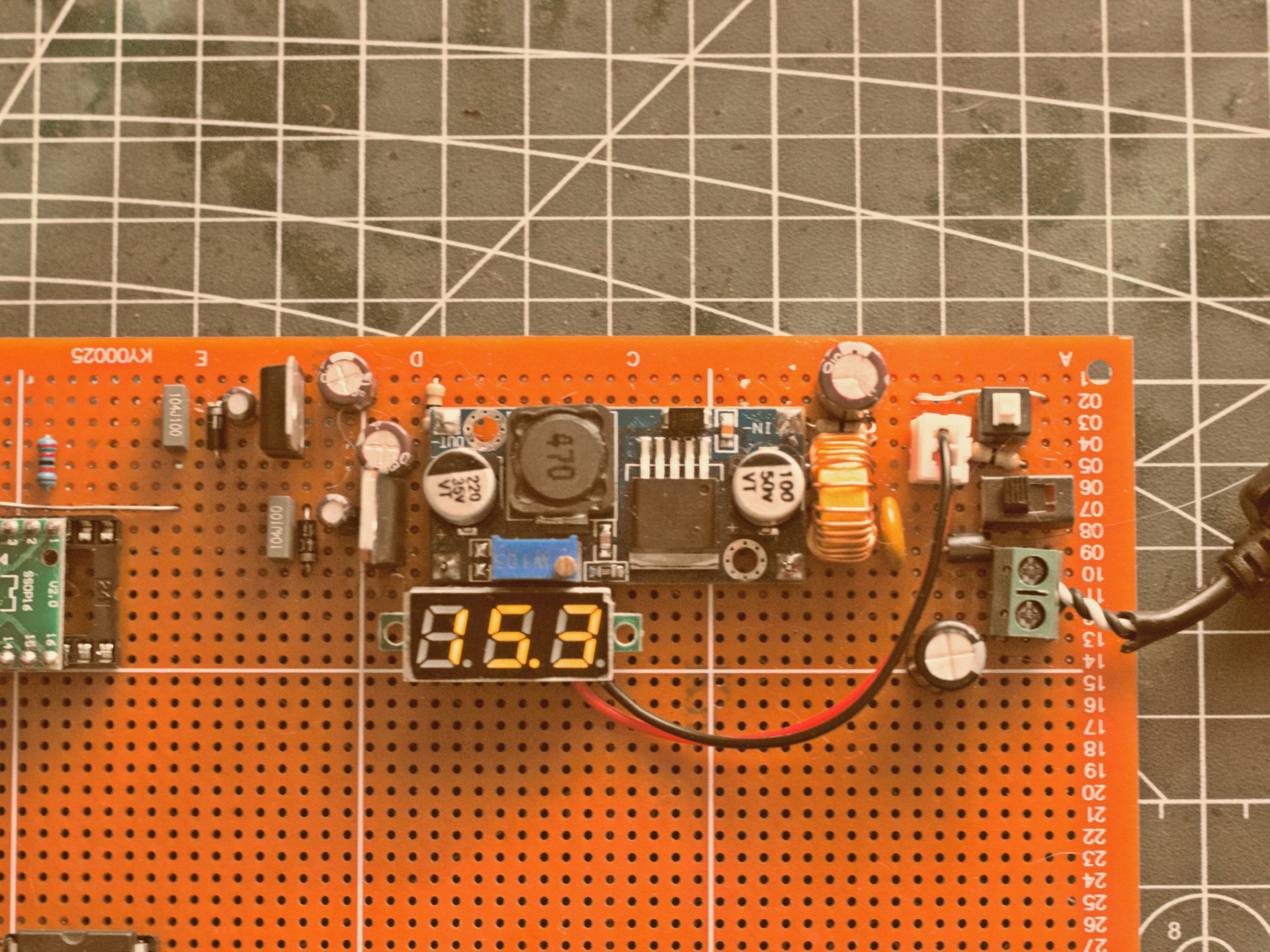
I added a voltmeter with dual modes to the circuit. When you press the button on the top right, it switches between two modes: one shows the main supply voltage entering the switch, the other shows the negative voltage at the inverter output.
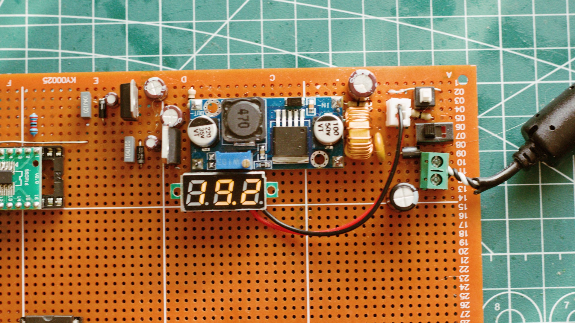
The photos show 19V and 15V—19V is the input voltage, and 15V is the inverter output.
Why?
Because I didn’t want to be stuck with only the 19V adapter. I wanted to be able to plug in whatever I get my hands on in the future—any adapter above 12V. That’s life; adapters come and go, the only thing that remains constant is the screwdriver in my hand.
My job is already to tame chaos, or at least to feel like I am, dammit. That’s why I didn’t want to hunt for a multimeter every time I swapped an adapter. Now all I need is a screwdriver: I turn the trimpot on the MT3608 module while looking at the screen—I set it to ±12V with any adapter 15V or higher. By eye, instantly, without hunting for tools here and there.
7. Tricking the Circuit: Converting Boost to Inverter
It was time for the inverter part. The MT3608 is technically just a positive boost module on paper. But with a little trick, you can turn it into an inverter.
All you have to do is trick the module’s reference frame:
- Connect the output (+) pin to real GND.
- Connect the output (-) and input (-) pins together.
- Provide the voltage from the adapter to the input (+) pin.
The module still does its job: it performs a boost relative to its own GND, thinking, “I’m boosting relative to GND here, man!” But we didn’t connect its GND to the real GND—we connected the real GND to its output. The result: the module’s own reference, the input(-)/output(-) node, falls below real ground. What’s left for us is exactly what we wanted: an adjustable negative voltage. The module, in its own dream world, thinks it’s still producing something positive—happy in its own ignorance, perhaps that’s the healthiest way to live, dammit.
This is exactly what I explained at the beginning: voltage is not absolute, it depends on the reference. The only way to trick the module was to change what it called “ground.”
Of course, there is a penalty for this: current is consumed 2 times more. The module establishes a power balance according to its own reference, but the real power flows according to real ground—the two don’t overlap. The price you pay shows up in your current budget. Nothing is free—nothing here, anyway.
8. Final Cleaning: Linear Regulators
I still had a raw voltage of around ±15V, fresh out of the boost/inverter. The MT3608 is an SMPS, after all—the output is still dirty.
The only way to really clean this in the Turkish market is the L78 and L79 series linear regulators. There is no other option—you won’t find anything on the shelves except these antique chips from the 1980s.
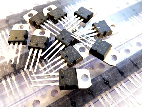
The logic of a linear regulator is simple: it drops excess voltage by dissipating it as heat. No switching, no chopping—it’s a pass element that acts like a constant, “stupid” resistor. The efficiency is bad, but these chips are 1-2 liras, they are in every device you lay your hands on, and despite being antique, they get the job done. Who gives a damn about the inefficiency, dammit?
In my case, this “stupidity” was exactly what I needed. It’s not a switching circuit—it doesn’t carry switching noise, it can’t even carry it. It takes that rough voltage and dumps it out as heat. I feel it lukewarm when I touch it—not burning, because the power dissipated isn’t that high. But if I had used a 20-25V adapter, it would probably be even redder; as the voltage drop increases, the dissipated heat increases too. (In old devices, they used to put small heatsinks, thermal paste, or sometimes even a crude pile of solder on these regulators—all solutions to the same problem: getting rid of the heat.)
Finally, I added two protection diodes to the output. The reason is latch-up. The originals of these regulators aren’t in Turkey—almost all you see on the market are Chinese clones, and there is no shortage of issues at the silicon level in the clones. If one rail is still up while the other falls, or if a situation like reverse polarity occurs, the parasitic structure inside the chip can be accidentally triggered and turn into a short circuit. The two diodes are a fuse against these scenarios: so that no pin of the regulator ever sees current in the reverse direction under any condition.
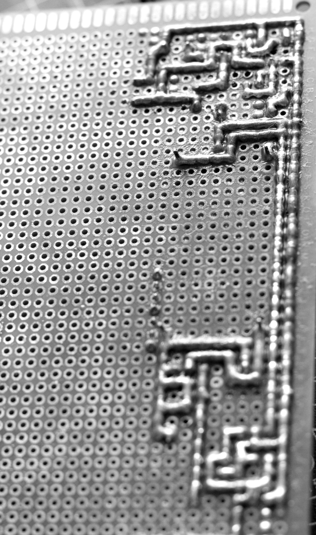
In the end, I had a power line that could output ±12V and hundreds of mA. Something that could be used for every job I take on, including the Analog PC.
(Actually, I don’t think I’ll use it for the Analog PC—the reason for that later.)
But let’s come to the main point: the CHUA circuit itself.
So, What Is This Circuit For?
I’ll give you the honest answer: it’s not for much of anything. It doesn’t touch your wallet, it doesn’t get a line on your CV, nobody knocks on your door saying “oh, you built that chaotic circuit.” The CHUA circuit will never practically change your life.
Then what is it for?
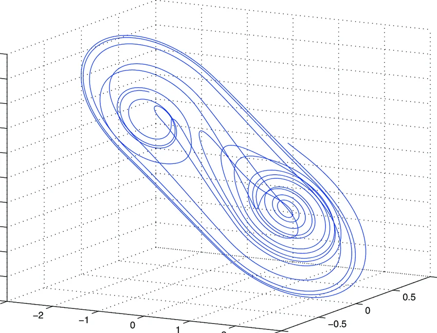
It takes chaos—what they call a “strange attractor” in mathematics, that movement which is unpredictable yet bound by precise rules—out of the paper and puts it in front of your eyes. When you look at it in X-Y mode on an oscilloscope, you see a shape that looks like two loops connected by thin spirals, a shape that never repeats itself: the double scroll attractor, known as Chua’s Scroll. 🌀 It’s the tangible, solderable form of what they call chaos.
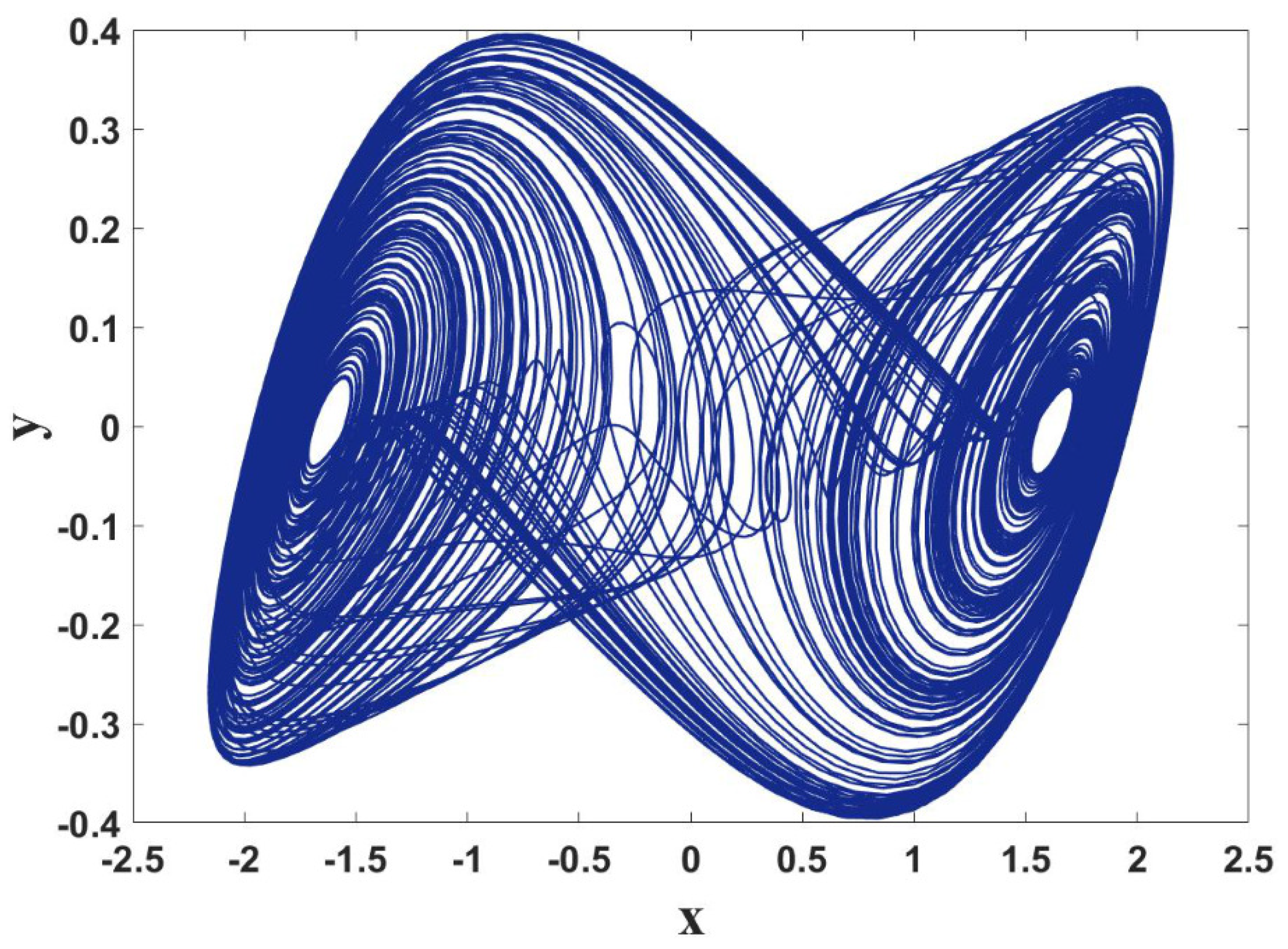
It’s not that there are no practical uses—chaos-based encryption, secure communication, random number generation (yes, another way to the same house as what I did at CTH). But let’s be honest: the main function of this circuit was never “practical.” Its function was to prove that chaos is not random noise but a phenomenon bound by precise mathematical rules—and the fact that it can do this with only 4 passive elements and one “fake” resistor shows that the universe is sometimes much less complex than it appears.
So: it won’t change your life, but it lets you fit chaos into the palm of your hand. For an active nihilist, there is no more satisfying uselessness than this, dammit.
Who is Chua, and How Did He Find It
When Leon Chua designed this circuit in 1983, he was a guest at Waseda University in Japan, not Berkeley. (He’s not a stranger, actually—he was the one who theoretically proposed that the “memristor” should exist as the fourth fundamental passive circuit element—along with the resistor, capacitor, and inductor—in 1971. That memristor business I dove into a few months ago, the debate about the physical realization using Chua’s mathematical framework—it’s all the same man.)

The background is simple: the Lorenz equations appeared in 1963, famous for the butterfly effect, but they had two shortcomings. First: they couldn’t be reliably reproduced with a real laboratory circuit—people were trying to simulate them with analog computers, but the result was always caught up in component tolerances, noise, and the ambiguity of “is this really chaos or is the circuit broken!?”. Second, and more strangely: it hadn’t even been mathematically proven that the Lorenz attractor was truly chaotic—this only became clear in 1999 with Tucker’s computer-assisted proof. So, for almost 40 years, everyone was trusting a system that only claimed to be “likely chaotic.”
Chua must have been unable to tolerate this uncertainty, so he chose his own path: instead of building a random circuit and saying “look, it behaves chaotically,” he built from scratch the simplest circuit designed to guarantee chaos, using piecewise-linear circuit theory. Not trial-and-error, but engineering. It was confirmed in 1997 with a computer-assisted proof that the circuit was indeed chaotic—2 years before Lorenz’s own. The “copy” was proven before the original—one of the rare examples of the universe’s sense of black humor.
The circuit itself is ridiculously simple: 2 capacitors, 1 inductor, 1 linear resistor, and a nonlinear element showing negative resistance that they call the “Chua diode”—it can be built with two op-amps or a few transistors and diodes. This last element pumps energy into the circuit; it is what compensates for loss and sustains the oscillation. The rest is as common as what you’d find in a high school lab.
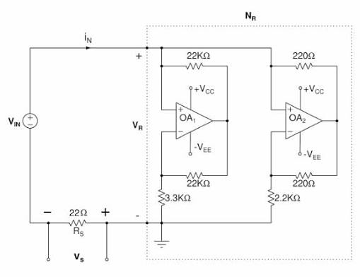
Bonus: most Chua circuits work in the audible frequency range—meaning you can actually listen to this chaos with your ears.
Chaos, a Few Hours, and a Moth
Chaos in mathematics is not “randomness” as you might think. On the contrary: the CHUA circuit is completely deterministic—if you start with the same initial conditions, the exact equations run; no one is rolling dice. The problem is this: it is incredibly sensitive to initial conditions. Even if you start with a one-in-a-billion difference, the system grows that small difference over time, and after a while, two “same” beginnings turn into two separate stories that are completely detached from each other. This is exactly what we call the butterfly effect: both precise and unpredictable, at the same time.
That’s why the oscilloscope output of the CHUA circuit never repeats itself. The circuit isn’t broken, and it’s not a miracle—that’s just how math works.
If you ask why I chose this project: because it was simple to make and it took me only a few hours. With the Analog PC on the shelf, I needed to drop something on the site—it had to be something that would finish in a few hours, yet be just as worthy of talking about. CHUA fit exactly into that gap.
And a bonus confession: Chua’s plot, that shape they call the double scroll, looked like a moth to me—I liked this similarity. Maybe not as poetic as Lorenz’s butterfly, a bit dimmer, a bit more like a night owl. But that’s fine—everyone has their own bug. (:p)
Conclusion
In the end, CHUA worked, and I saw the fluttering wings of chaos with my own eyes on the screen of my first oscilloscope—that moth I mentioned earlier was really there, spinning endlessly around itself in X-Y mode.
The oscilloscope itself is a separate story. It doesn’t have a proper video recording feature. Being Chinese-made, the learning curve took on a peculiar strangeness of its own—I wandered through the menus blindly for a while, with no idea where any button would lead. It will settle in time, I suppose, like everything new.
But for now, I’m taking a break from hardware. A few months—no fixed date—(there are other pieces of hardware, nearly finished. if I find the time, I’ll finish and share that one too before taking a break.), and if there’s one thing I learned through this article, it’s this: some things don’t progress by a calendar, but by their own initial conditions. For this period, I’ll turn from soldering smoke to art; I’ve really missed it. And I think it’s time to pursue more “work that truly touches life,” and to venture into some adventures in my private life (;).
Actually, throughout the entire article, I talked about only one thing: a single-ended supply can never see half of the wave. Without the negative, the circuit remains incomplete, the signal clips—all or nothing. If I look at myself, for a while now, I have also been working too single-endedly: always the same reference, always alone, always connected in series… and showing only one face of my life. Maybe it’s time to find my own ground—to look at the other half of the wave. Maybe it’s time to connect in parallel, not in series: so that when one node goes, they don’t all go, staying connected to the same line.
I learned how to take chaos out of the paper and put it before my eyes in this article. Next—I think—the harder and definitely even more fun one: taking it out of life itself.😉